
Views: 14
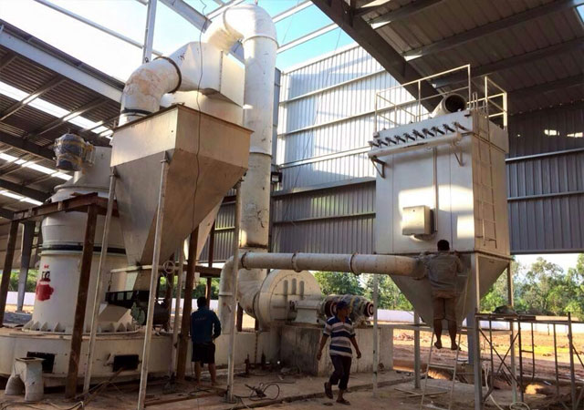
Raymond Mill Installation Steps
Step1, Line: carefully see the Raymond mill foundation map, according to the excavation map line.
Step2. Pit excavation: the depth of the main engine (3500×3500) shall be no less than 2900mm within the position of the main engine (3500×3500) according to the requirements of the drawings.The depth of the rest can be determined according to the actual conditions of the foundation.
Step3, Elevation and die: after the pit is dug, according to the base elevation icon for the corresponding position height.
Step4, Put the mold cloth: in the main machine anchor bolt hole in the cloth, the rest according to the local actual decision.
Step5, Pouring concrete: ensure that the cement label in more than 400, when the concrete poured to the elevation position, pay attention to the mold, and ensure the relative size of each position.Check whether the wooden mold is displaced when pouring, if there is a wooden mold displacement should be corrected in time.After correcting the correct position relation, continue pouring and keep vibrating the vibrator's vibrator to ensure its quality.If it is freezing season, heating measures must be taken. The Raymond mill maintenance period is 12 days after pouring.
Step6, Main Mill in place: because the main mill in the process of installation and hoisting may appear on the central shaft of the main mill channeling.The way to judge the center axis is as follows.
If it is found that the gap between the upper end of the coupling and the gland is less than 20mm, it means that the center shaft of Raymond mill has been channeling.At this time must use a sledgehammer to hit the plum stand on the middle of the center to reset the center axis.Otherwise, when the reducer is in position, the fixed half coupling below the main mill and the active half coupling on the side of the reducer will create a false impression of successful installation because the clearance is 5mm.When the main mill works to a certain time, the central axis is reset under the action of gravity.The gap between the two half-couplings will be gored to death by elimination.Thus will lead to the host load is too large, can not afford to give materials, low output, host vibration problems.It is even possible to break the casing of the reducer.So after the main mill is in place, be sure to check the gap between the two half couplings according to the technical drawings.The main mill base should be aligned with mat iron and level with frame level.The longitudinal and horizontal level of the main engine shall be no greater than 0.1mm within 1000mm.The different coaxiality of the two half couplings shall not be greater than 0.3mm.The gap between the two half couplings should be kept within the range of 5-8mm, and the degree of non-parallelism should not be greater than 0.1mm.Blower housing (installed with tee pipe) with the main air return box mouth cavity as the reference air conditioning housing and blower seat.The second grouting can be carried out after in place. When the second grouting is close to the bottom plane of the main engine base, the steel plate with concave type specification of 300×300 thickness is used to pad the anchor bolt of the main engine and fill it with mud. The machine can be started after the warranty period of 18 days.
Step7, Classifier and pipeline installation: according to the technical drawings to do the grader support frame and cyclone support frame, and according to the position shown in the drawings to put the support frame.
Hoist grader and cyclone collector on the corresponding bracket, according to the drawings to connect the pipeline.


